From Ice Cream Sticks to Inverse Kinematics: How Trigonometry Brings Robot Arms to Life
A few years ago, in 9th grade, I built my first robot arm out of ice cream sticks and tape. It was a simple two-jointed mechanism: the…
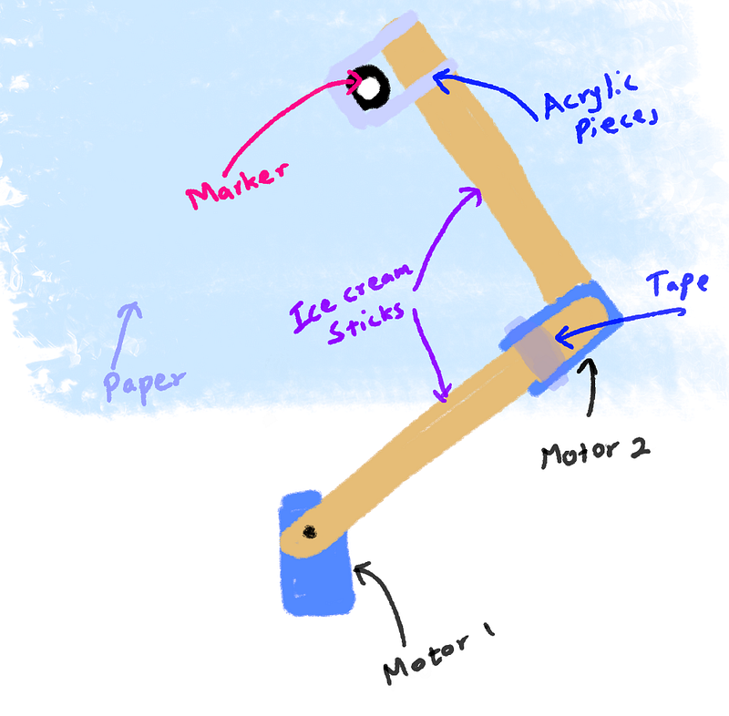
A few years ago, in 9th grade, I built my first robot arm out of ice cream sticks and tape. It was a simple two-jointed mechanism: the first arm connected to a servo motor, and the second arm attached to another servo at the end of the first. My dream was to turn it into a plotter, stick a marker on the tip and make it draw whatever I wanted.
The build wasn’t pretty, but it actually moved. The servos responded when I sent them angles. The real problem appeared the moment I tried to connect it to my Arduino and use it as a plotter.
Servos only understand angles. But to draw something, I needed to give the arm X and Y coordinates. How do you turn a point on paper into the exact angles for two servos? That’s when I first heard the term Inverse Kinematics.
I did a quick search, saw a bunch of scary equations, and immediately gave up. At that time I barely knew basic trigonometry, let alone mechanics. So the project sat on the shelf for years.
Recently, while cleaning out old electronics boxes, I found the dusty arm again. This time I had a much stronger math background. I decided it was finally time to finish what I started, but smarter.
Instead of risking the real hardware right away, I built a simulator first.
I opened Qt Creator (I already knew the IDE, so it felt comfortable) and started coding a desktop app in C++.
Step 1: Drawing the Arm on Screen (Forward Kinematics)
Before solving Inverse Kinematics, I needed to reliably draw the arm. That meant implementing Forward Kinematics, calculating the end position when you already know the angles.
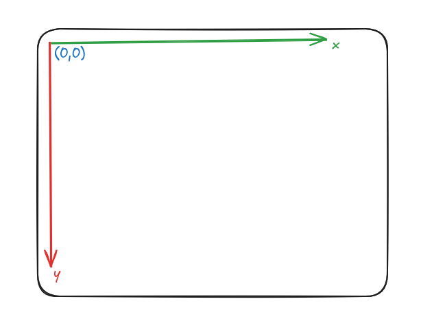
One important detail: computer screens measure coordinates from the top-left corner, with Y increasing downward. In normal math, Y increases upward. So we have to flip the sign on the Y calculations.
I created a simple struct to represent each arm segment (“rod”):
struct Rod
{
    double startX = 0;
    double startY = 0;
    double endX = 0;
    double endY = 0;
    double length = 100;
    double relativeAngle = 0;
};
Here, the start and end coordinates are what you think they are. The relative angle is the important thing here, it’s the angle of the rod, relative to the previous rod. This is the angle that I was referring to as the servo motor angle.
However, when dealing with the canvas we need only two things, the start and end coordinates of a particular rod.
void FKCanvas::paintEvent(QPaintEvent *event) {
    QPainter painter(this);
    // Some stuff to make the canvas look better
    painter.setRenderHint(QPainter::Antialiasing);
    painter.fillRect(event->rect(), Qt::white);
    QPen pen(Qt::blue, 3);
    painter.setPen(pen);

    // Actual code that draws the line
    painter.drawLine(rod.startX, rod.startY,
                         rod.endX,   rod.endY);
}
But, Finding those two points is another challenge.
For the first rod, I placed the base at the center of the canvas and treated its relative angle as the angle from the positive X-axis (Just how I like it):
rod.startX = width() / 2;
rod.startY = height() / 2;
Also for the first rod, I took the relative angle as the angle related to the x axis for convenience.
So, to find the end coordinates of the rod, we just apply our good old sin and cos inverse.
rod->endX = rod->startX + rod->length * std::cos(relativeAngle);
rod->endY = rod->startY - rod->length * std::sin(relativeAngle);
Did you notice the negative sign for Y coordinate? Well, that is to compensate the issue where our y coordinate is inversed in the canvas.
For the second rod, we calculate it’s absolute angle by adding it’s relative angle to the current absolute angle value. And set the start position as the end position of the previous rod. (We do this in an iterative way for the rest of the rods.)
for (int i = rodIndex; i < rodCount; ++i) {
    Rod* currentRod = &rods[i];

    if (i > 0) {
        Rod* previousRod = &rods[i-1];
        currentRod->startX = previousRod->endX;
        currentRod->startY = previousRod->endY;
    }

    currentAbsoluteAngle += currentRod->relativeAngle;
    currentRod->endX = currentRod->startX + currentRod->length * std::cos(currentAbsoluteAngle);
    currentRod->endY = currentRod->startY - currentRod->length * std::sin(currentAbsoluteAngle);
}
So this gives us a cool robot arm simulator.
Step 2: Inverse Kinematics — Turning Coordinates into Angles
Now, I had everything I needed to make an Inverse Kinematics solver.
Practically we cannot use Inverse Kinematics for a system with more than 2 rods, as there can be infinitely many solutions.
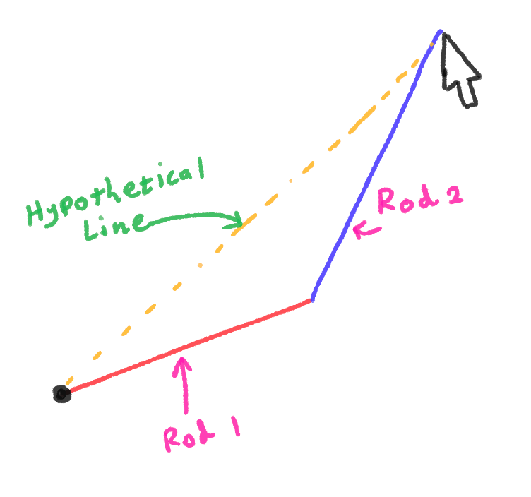
I created a two rod setup as the above, and connected the first rod to the center of the screen. And end of the second rod to the mouse pointer coordinate.
Now all I have to do is to figure out the angle of the two rods given that I already know the lengths of the two rods.
Particularly, what we need here is the Cosine Law
Imagine the two arms and the straight line from the base to the target forming a triangle. We know all three side lengths:
- a = length of first arm
- b = length of second arm
- c = distance from base to target (calculated with Pythagoras)
So, since we know the lengths of all three sides, we can apply
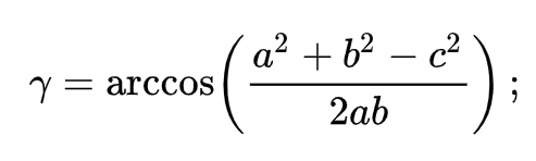
This is the exact code that does that:
void IKCanvas::updateEndRod(double x, double y){
    Rod *rod1 = &rods[0];
    Rod *rod2 = &rods[1];

    rod1->startX = width() / 2;
    rod1->startY = height() / 2;

    double dx = x - rod1->startX;
    double dy = -(y - rod1->startY);
    double distSq = dx * dx + dy * dy;
    double dist = sqrt(distSq); // Use Pythagoras theorem to find the length of the third side

    // Find a, b, c
    double a = rod1->length;
    double b = rod2->length;
    double c = min(dist, a + b); // This is to avoid errors, when mouse pointer moves out of range

    double internalAngle1 = acos((a*a + c*c - b*b) / (2 * a * c)); // apply cosine law for the first angle
    double absAngleToTarget = atan2(dy, dx);
    double absAngle1 = absAngleToTarget + internalAngle1;

    rod1->endX = rod1->startX + rod1->length * cos(absAngle1);
    rod1->endY = rod1->startY - rod1->length * sin(absAngle1);

    rod2->startX = rod1->endX;
    rod2->startY = rod1->endY;

    double elbowAngle = acos((a*a + b*b - c*c) / (2 * a * b)); // Apply cosine law again for the elbow angle
    double absAngle2 = absAngle1 - (M_PI - elbowAngle);

    rod2->endX = rod2->startX + rod2->length * cos(absAngle2);
    rod2->endY = rod2->startY - rod2->length * sin(absAngle2);

    update();
}
And here’s the simulator in action — the arm now follows the mouse perfectly!
(Note that for each position, there can be two solutions, in this demo I only consider one solution)
What’s Next?
This simulator was just the beginning. My next step is to build a canvas where I can actually draw a line or shape, and have the arm trace it smoothly.
The ultimate goal? Mount a real marker on the physical arm and turn it into a working plotter that draws on paper.